
INTRODUCTION
There are many possible upgrades to the rear brakes. The following articles outline several methods. Brakes are serious business, be careful.
INSTALLATION PROCEDURE (kit from Stainless Steel Brakes, BAT or Rapido)
Tools needed: 41mm socket (available thru NAPA with < drive) < to adapter Torque wrench 250 ft pounds ( can be rented ) flaring tool that will do a double flare ( can be rented, sometimes at no charge ie: TRAK Auto ) Floor jack or a lift Safety stands " breaker bar Pipe about 1 I.D. and 3 - 4 ft long to extend breaker bar for removal of axle nuts. Assorted other metric wrenches and of course a Merkur fine adjustment tool (hammer)
Supplies: Good quality DOT3 brake Fluid - recommend Ford Shop cloths Plenty of time and patience
Helper tips for the Stainless Steel Brake kit (also sold through BAT & Rapido).
1) Be sure to check the inventory sheet to make sure you have everything. My kit was complete EXCEPT for the 3/16" male brake line fitting (part#1412S) which is used on the original brake line after you cut into it(installed BEFORE flaring), replacing the proportioning valve. Note -the parking brake springs (0518 & 0519) are already installed on the calipers, and "part# 9969" is actually just a note to tell the kit builder to install the springs.
2) Should you decide to replace the rear bearings, remember that you will need 2 on each side as well as 2 seals on each side. Don't even think that you'll be able to re-use the seals - you will destroy them upon removal, and removal is required to get the bearings out. Don't even ask me how you remove the bearing races - mine looked okay after cleaning, so I just re-packed and dropped in the new bearings. The seals pressed in with a vise with only a little trouble.
3) Below are some notes/corrections to the Rapido instructions which are included with the kit from SSB. The numbers and letters correspond with the ones in the directions:
2a) Wheel bearing nut is 41mm, not 40mm. Take the car to a shop with a 500+ ft/lb air wrench to loosen these if you don't have one yourself.Note - the driver's side is left-hand (reverse) threaded.
2b) A slide hammer will help greatly in removing the wheel mounting flange (also helpful in removing the old brake drum).
2c) Parking brake cable retainer has three ears - grab two with a pair of pliers / Vise-grips and push on the third with a screwdriver as outward pressure is applied.
2d) A brake-line pinch tool on the inboard rubber lines will prevent most of the fluid from spilling all over.
3c) Don't over-tighten the splash-shield screws into the mounting brackets.
3g) The instructions are wrong! The parking brake lever/spring shouldbe positioned towards the front of the car (about 12 o'clock), not the rear. Also ignore the LH and RH stampings on the levers - these are also wrong! The longer of the 12mm bolts is used (with the spacer and lock washer) on the center-most hole, which also secures the "L" bracket. The"L" bracket should be positioned so that the forward section (where the bend is located) is somewhat lower than rear section (where the securing bolt is located).
3h) The plastic barrel nuts are located near the drive-shaft, next to the fuel pump. You'll need to pull the locking plug out with a pair of pliers first. A liberal spray of rust penetrant would be very helpful here to loosen things up. Unscrew in a counter-clockwise manner (from the rear of the car) to loosen the cable. You should be able to unscrew these for a couple inches, which is what I suggest you do to get as much cable play as possible.
3i) The instructions imply that you should have 2 washers on each side,but only a total of 2 are supplied. I actually didn't use any - so far,no problem.
3l) The car does NOT need to be on a lift to perform this task.Removal of front left wheel is required however. Jack and block this corner up for safe and easy access. 3m) 3/16" flaring tool/fitting is needed along with a mini pipe cutter,file, and de-burring tool. Remember, you can always cut more pipe off, but you can't glue more back on! It is a bit of a struggle bending the new pipe into place - be careful not to break the plastic pipe retaining clip.
Conclusion:
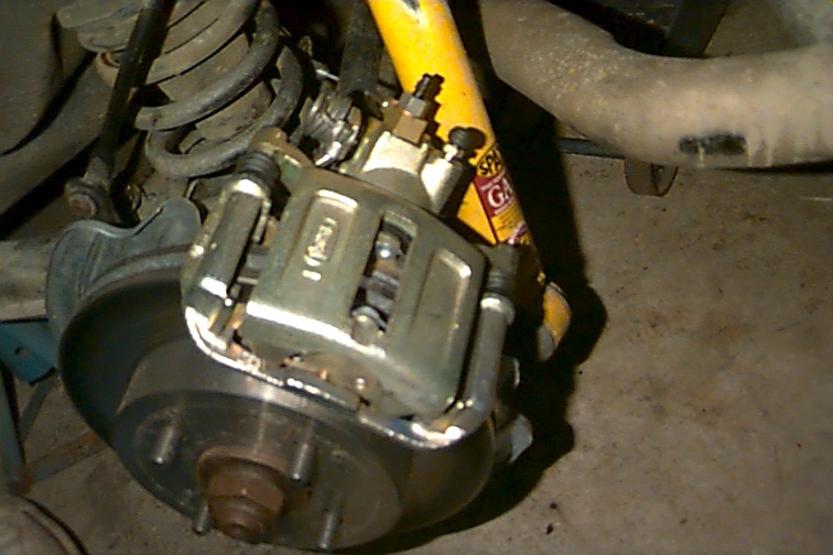
INSTALLATION PROCEDURE (87 or 88 Thunderbird Turbo Coupe parts)
All the following parts can be sourced from any 87 or 88 Thunderbird Turbo Coupe.2 rear disk brake calipers.
Where this kit is better than the Cosworth rear disks is that the Cosworth utilizes a solid non-vented rotor, prone to easy warping under extreme use. The Cosworth parts are expensive and are not available at the corner partmart. The T'Bird parts are just about available anywhere and are very affordable. Biggest plus is that the T'Bird is a heavy car so these rotors are 260mm diameter and are vented they will outlast the Cosworth parts.Caliper parts are readily available should you ever have to rebuild the units.So you know I phoned Stainless steel brakes to try and source the mounting brackets and they refused to sell these parts separately.They (Marvin) did tell me that the kit including all the necessary parts is available this month on sale for $700 American sale price. So I am making my own brackets. I will be cutting a trial mockup this weekend to ensure this design is aligned and does not interfere with any suspension components. If all goes well I will consider producing this part for resale to the Merkur masses if there is a demand.Some things I left out of post on the T'Bird rear brake conversion.I did source my calipers from a local scrap yard at a price of $125.Canadian dollars. They required new dust seals and boots at $13 each. Serviceable parts available for this caliper include piston seals/dust boots/pistons/slider pins/slider pin dust boots.I used new rotors and brake pads on my conversion. This conversion will require an after market proportioning valve with bias of approx 70% front/ 30% rear or adjust to taste. For the hand brakes you can use the stock cables with some modifications.Finally the rotors fit like a glove. Before doing this conversion I consulted with a friend (Dan) who is an salesman at KVR/Best Price auto parts In Ottawa where I live. This is the kit they sell for big bucks for the XR4. They purchase from Stainless Steel Brake company directly.My reason for doing this is that the XR4 should have had these brakes from the factory especially considering the cars capability for speed.With that said this will also make servicing the brakes in the future a lot easier. I did consider the kits offered by BAT and Rapido but as I understand that these use Scorpio disks and calipers. Reason for not going that route aside from the aforemention reasons (see last post) is the price of a single Scorpio caliper cost more then the my whole conversion project.
I though of using 1/8 because the Slider pins/cage/or pad support for this caliper is already tapped to accept a bolt. This will facilitate bolting the slider up to the mounting bracket. Initially I though that 1/8 might be to thin but the bracket follows the outline of the bearing carrier and bolts between bearing carrier and the swing arm for extra stiffening. There is only a area of about 3/4 (ears) to bolt to protruding past the bearing carrier. I will try this hoping for no problems. After studying the pictures from other (Rapido/BAT) brackets and the thickness of the backing plate which is bolted between bearing carrier and swing arm I concluded that using anything thicker here will interfere with the hubs ability to stay within the splined section of the lower double offset joint axle. Of course you might consider designing the bracket to bolt over top of the bearing carries.
If considered maybe for the DIY's you could post the design template in the Merkur encyclopedia.
INSTALLATION PROCEDURE (XR4Ti calipers with larger pads and SVT rotors)
I spent a lot of time (and money) finding the right pad. That said, you can use the stock pad and still have a gain in braking, because the calipers are moved out.I have figures.
My proto brackets are done, but I am trying to work with a guy at work who does CNC stuff to get them made en masse.They aren't on the car, as I was too lazy to make a third,and needed samples for him.
The problem (time wise) is a small bump on the existing caliper bracket which requires a small milled out section in the adapter bracket. Ooh, that was a secret. Anyway...
I don't think vented rotors at the rear are critical,at least for a road car.
At the front however I think the SVT rotors could make a big difference.
INSTALLATION PROCEDURE (Scorpio Rotor and Caliper)
I made up an adapter plate from 5/16 medium grade steel plate . The plate is approx 5 1/4 by 4 3/4 it has a3 1/8 hole centered at 2 3/8 and 1 3/4 up from the bottom This slides over the bearing housing and then you can line up and drill through the four mounting holes from the removed backing plate. The exces which is to the top is shaped into two ears to pick up on the Scorpio calipers. I made my first template out of thin aluminum just to check fit and then made it from 5/16 as that gave me the correct spacing . For the rotors I used after market Scorpio, and using an old front rotor drilled three new holes and elongated the other one, you can drill the holes large as the rotor centers on the center hole (hub centric).The handbrake cable is Cosworth part #1656793 and is less than $45 and I ordered mine from Andy at Burton Power in England fax #0181 5544828. This set up has worked extremely well and given no trouble at all.
INSTALLATION PROCEDURE (proportioning valve for rear discs)
Take the valve apart and remove the spring and reassemble, the piston will bottom out and be ineffective. This is the way SVO does it on the Mustang rear disc conversion.